
Roland PMA-5 Backlight

Look at that lil beaut!
I can’t believe it either!
The Hive Mind was able to develop a way to adapt our TR-505 backlight kit to fit the Roland PMA-5 “Personal Music Assistant”
This thing is a wild little slice of history, from a VERY brief period of time between cell phones and smart phones, where the Personal Digital Assistant was the mark of a true technophile. I never had a PDA of any kind - I had a digital address book that pretended to be a PDA…more than enough for any 90s highschooler!
This thing had it all for its time - 4-track midi sequencing with chord builder and rhythm section, midi output…even a stylus and a TOUCH SCREEN. It really was the future back then, wasn’t it?
Anyway, here are the instructions for the SUPER-simple installation. These aren’t subject to the same screen darkening issue as the TR-505, so this is a quick and easy upgrade. You’ll just need a backlight kit (available HERE) and soldering setup!
Begin by removing the 6 screws from the back of the case and setting them aside where you won’t lose them. Please don’t lose them! If you can’t find screw #6, it’s inside the battery compartment. Next, remove the screw and fold back the top panel (figure 1 below)

(Figure 1)
There’s one silver screw holding this panel in place, but it might be tough to spot. Near the top

(Figure 2)
This is what the ribbon connector looks like when it is locked into place.

(Figure 3)
This is an ribbon connector unlocked so that you can insert or remove the cable
Disconnect the ribbon cable by unlocking it as shown in figures 2 and 3. This is a standard ribbon cable lock, but this could be your first one!
Next, remove the 4 screws holding the LCD driver panel to the housing. The panel itself will connected to the board with some elastomeric “zebra strip” connectors. remove the screen and connectors, which are (believe it or not) only held in place because of the pressure over time and don’t require any sort of adhesive.
Then, replace the front screen, making sure to place it right-side-up when viewing the front of the case.
You’ll notice some ink on the back of the LCD panel. This is going to show through under the backlight, in reverse. I tried removing it with rubbing alcohol, turpentine, and cleaning wipes and wasn’t able to get through and stopped there, not wanting to damage the plastic itself. If you find a way to remove that stuff, please let me know!
Place the “Honeycomb” side of the panel (fig 4) down so that the wires come out of the left side of the panel, and secure the right side with a small piece of clear tape. You want to have this as close to centered as possible, in order to illuminate all of the crucial areas of the display (fig 5)
Next, slide the NEW elastomeric strips in at the top and the bottom of the display. These new strips add another mm of space between the LCD and the driver board in order to make room for the LED panel. In a beautiful piece of engineering, these “new” strips are actually recycled from the TR-505s that I’ve upgraded with screens - a perfect fit! When placing the strips, it helps to get the whole section into the groove as much as possible. If the LCD doesn’t seat properly you can come back and mess with this later.
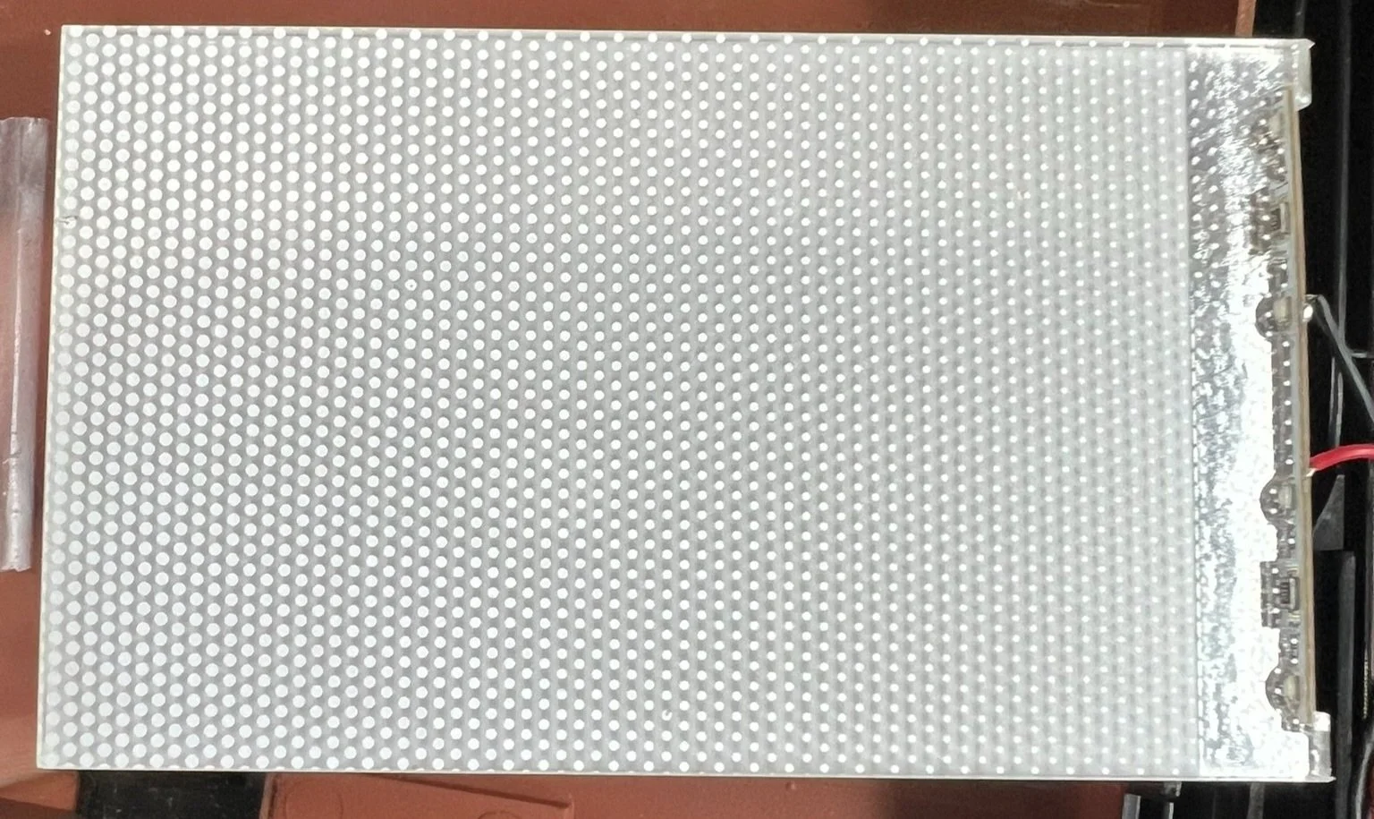
(Figure 4)
This is the “honeycomb” side of the LED panel that goes up against the back of the LCD screen

(Figure 5)
Note that the wires are coming out of the left side of the LED panel
Next, re-attach the LCD driver panel, making sure to line up the hole at the bottom with the positioning peg as shown in fig 6 - this is going to assure everything aligns properly and the screen functions as it should.
Next, add the screws securing the screen - but as illustrated in fig 7 in order to assure everything seats properly. You’ll want to add the screws in numerical order, tightening each one only enough to hold it in place - don’t fully tighten until all 4 screws are in place. When you do tighten the screws, tighten them in the same order. A little bit of bowing in the center of the circuit board is normal here, but this should get everything lined up nicely.
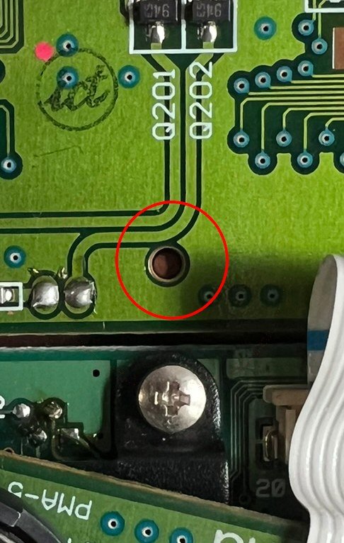
(Figure 6)
There’s a little peg that fits into the hole to make everything perfect. EVERYTHING. PERFECT.

(Figure 7)
Add the screws in this order, but don’t fully tighten until all 4 are in place, then tighten in this same order.

(Figure 8)
Solder the red and black wires near the power switch, as shown here.
Run the red and black wires from the LED panel around the left side of the board, and solder them into place as shown in fig 8. Lastly, reattach and lock the ribbon cable as shown way back in figures 2 and 3, and reattach the back of the housing - being extra careful not to catch the LED panel wires in the process.
And there you have it! Now all of your night PMA-ing can be a reality formerly only found in dreams.

