
Rebuilding/Repairing the LCD Display on a Roland TR-505
After years and years of dealing with those greyed-out TR-505 displays, I think I have finally found a DIY solution. As long as you have a screwdriver, tweezers, and a sheet of white paper, you can do this too! This said, I'm going to make you relive my troubleshooting process before we get to a solution.


I got my first TR-505 back in 1998. I found it at a yard sale for $5. FIVE DOLLARS. From that point on I've been hooked. I can say with no exaggeration - close to 50 of these have passed through my hands since. I love the default sound set, the programming is super-intuitive...and they are fantastic for modifications. I often have at least 1 or 2 for sale in my store, but they tend to sell out quickly!
Anyway - I digress. For some reason, half of the 505s I've encountered have this issue with the display. What causes it?! Sunlight? Heat? Smoke? Negative energy? Who knows? I don't, that's for sure. I've never wanted to experiment with a GOOD display to find out. I finally decided to roll the dice and try dismantling one of these bad boys to get to the root of the issue.
The first step for repair is to open up the TR-505 and remove the LCD and associated board. If you need instructions for that - stop here. This may not be the project for you. Shoot me a message of some kind and I'll take care of this for you!

Once you remove the LCD board, you should have what appears in the image to the right. The LCD screen itself is "stuck to" the board with this nifty foam connector. When I first disassembled this I was super-careful about not disconnecting those strips from the screen itself. It will make your life easier if you can do the same, however if they come off it isn't the end of the world - you just may need to do some additional troubleshooting later in the process.

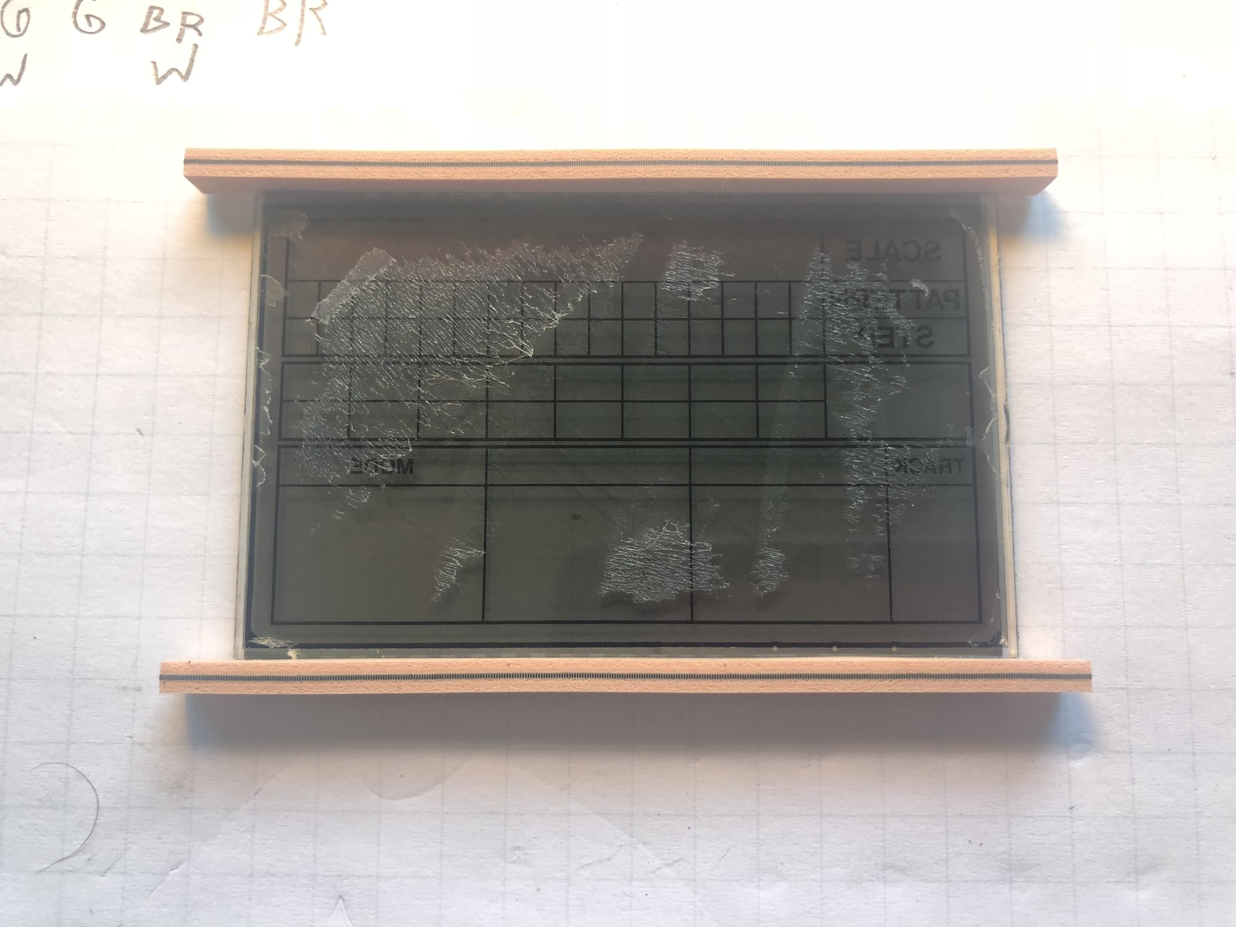
ANYWAY - once you get that board out, the next step is to remove the LCD assembly from the board. It should sort of peel off on those foam connectors. Again - if you can, try to keep them connected to the screen itself, so that you end up with something like the image on the left. Keeping those foam connectors on the top and bottom is great...but it's going to get harder and harder as we progress.
The next step is to remove the LCD backing. This is the root of all of these display issues. You want to grab one of the corners and peel back slowly using tweezers. WARNING - THIS SMELLS TERRIBLE. It's likely some sort of noxious fume that has forever damaged my interior. It smells like VERY strong vinegar - like a photo developing solution, for those who have encountered it. Once it peels, you should now have the two pieces shown below.

Clean the extra adhesive off of the back of the LCD with rubbing alcohol. and we're really actually truly almost done! At this point you'll want to put the LCD display back into the front panel of the 505 as shown in the image below. BE SURE TO PUT IT IN RIGHT SIDE UP SO THAT YOU DON'T HAVE TO DISASSEMBLE AGAIN LIKE SOME PEOPLE I KNOW.
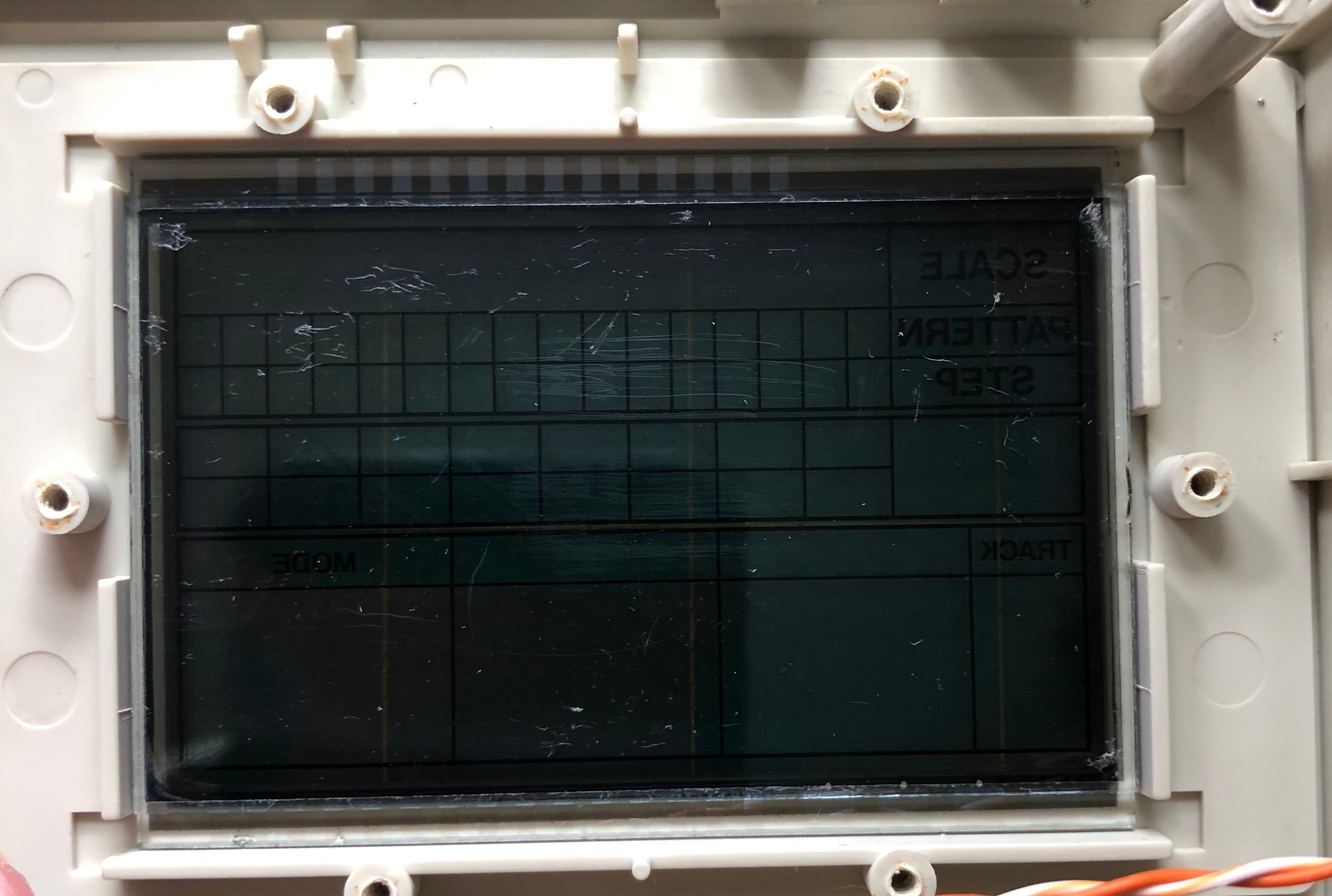
You may notice that those foam connector strips are missing in that photo. They came off for me, but I'll get into how to fix that shortly.
I agonized over this next step. See, that piece we peeled off is what makes the LCD visible. Without it you're just going to see the guts of the machine with very little actual display. That backing is what reflects light back so that you can make out the characters on the display. I tried lots of replacements for that backing. My first thought was a neon post-it I had lying around. Surely this must be bright enough!
It wasn't!
I then 3D printed a glow in the dark panel out of PLA, thinking it would function as a backlight after "charging".
It didn't!
I purchased some thin sheets of adhesive mirror paper, thinking THIS has to be the best way.
It isn't!
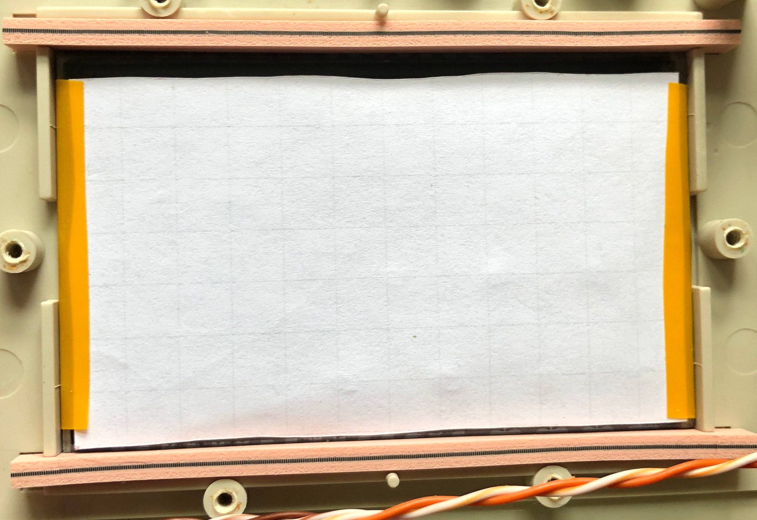
What finally did the trick was a plain old piece of printer paper, cut to 79mm x 48mm. I secured this to the sides of the display with electrical tape and am still refining this part of the process. If you have another idea, please tell me!
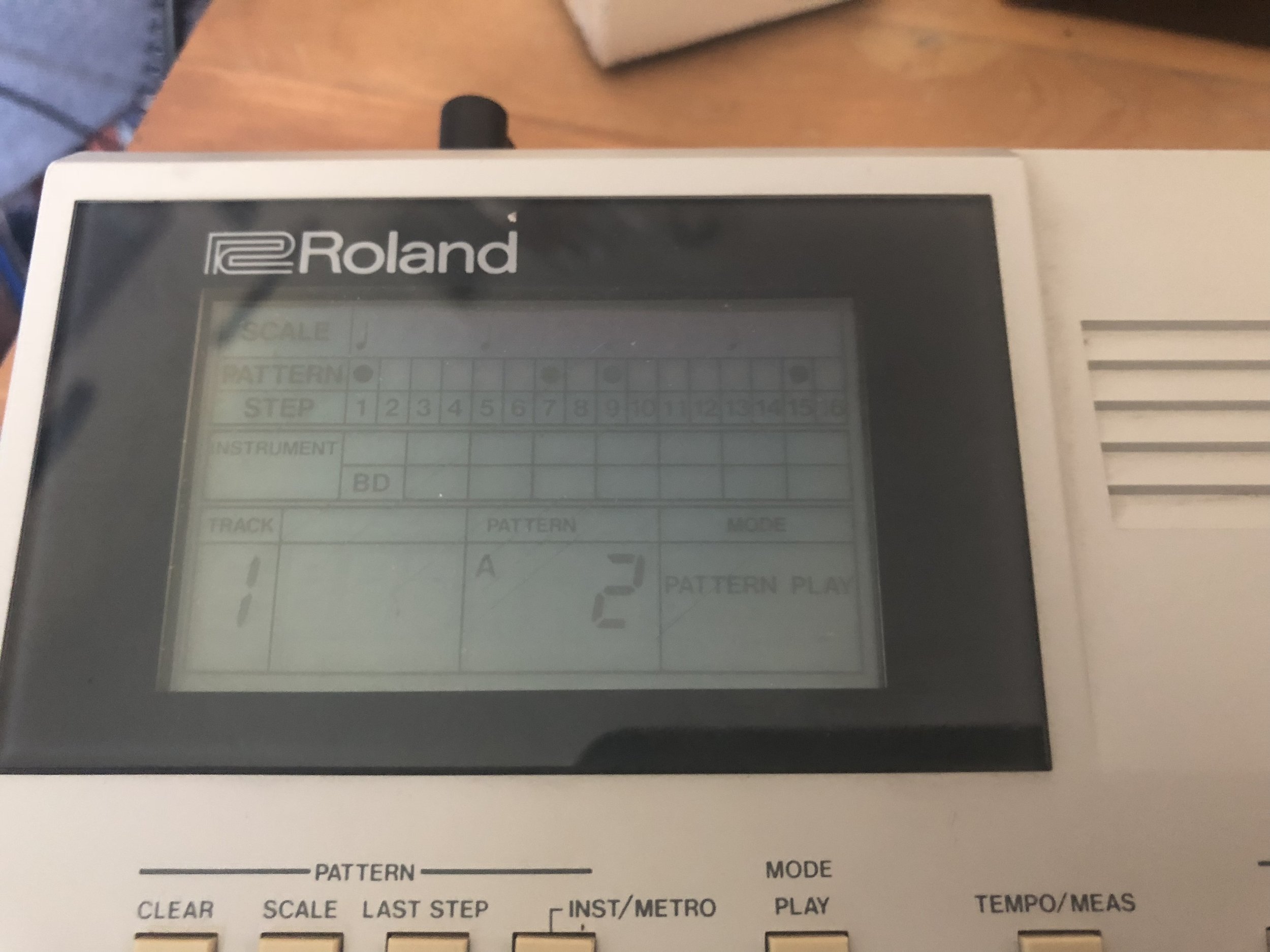
At this point I reconnected the foam strips just by laying it on top of the board. It fits together very easily this way - I imagine this is how the machines were constructed at the factory. One you have this together, screw the LCD board's other piece (the one we removed long ago) back into place, reconnect the wires, test everything by powering on before sealing the machine up, then close the machine up and you should be done! Or not! The first time I did this the LCD only displayed a portion of the information. I had to open it back up, nudge the foam to one side a bit and reconnect everything, then it was nearly perfect. I may try to get some more luminescent paper in the future, but this looks amazing compared to the machine's earlier state.
The next project is finding a way to wire this up with a backlight. I know it has to be possible, but with very little clearance between the display and the board it's a bit tough. Currently experimenting with 3D printed diffusers and rectangular LEDs, but we're still not quite there...yet.